Rapid Mate EMI Filter Connectors
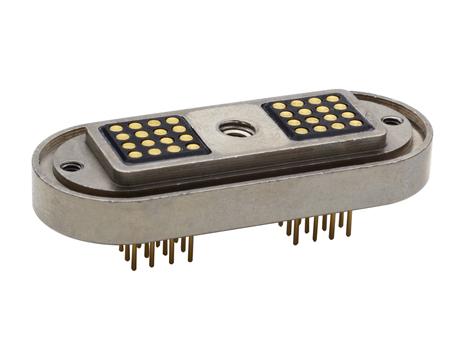
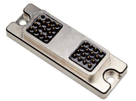
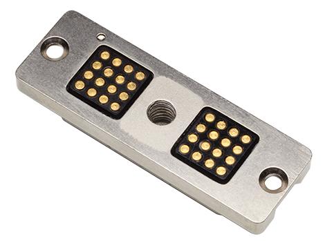
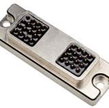
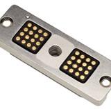
These connectors provide the ease and reliability of Hot Shoe style mating with the added benefit of integral EMI filtering.
Rapid Mate connectors offer mating via spring-loaded, compliant contacts. This method provides a rapid connection with low mating force and allows for some misalignment during mating. These contacts also provide a positive mating force to ensure a reliable connection.
Spectrum Control can design an EMI filtered, Rapid Mate connector, specifically for each application, providing the advantages of HotShoe style mating with required EMI filtering to ensure system functionality in electronic interference prone environments.
- Custom EMI filtering
- 100% tested before shipment
- Rugged and reliable
- Resists sand, dust, and water
- Low, flexible mating force
- Military and commercial communication systems
- Thermal and ambient light imaging cameras
- Docking stations
- Scanners
| Part Number | Capacitance | WVDC | Current Rating | Terminal Type | Description |
|---|---|---|---|---|---|
| 58-001-011 | Unfiltered (10pF Max) |
100 | 5A Max. | PC-Tail | Unfiltered, pin 8 grounded to housing |
| 58-001-014 | Unfiltered (10pF Max) |
100 | 5A Max. | Solder Cup | Unfiltered, pin 8 grounded to housing |
| 58-001-015 | Unfiltered (10pF Max) |
100 | 5A Max. | PC-Tail | Unfiltered, all lines insulated |
| 58-002-001 | 1750pF +/-20% | 50 | 5A Max. | PC-Tail | All lines filtered except pin 8 grounded |
| 58-002-002 | 1750pF +/-20% | 50 | 5A Max. | Solder Cup | All lines filtered except pin 8 grounded |
| 58-001-005 | Unfiltered (10pF Max) |
100 | 5A Max. | Figure A in Data Sheet | Complete assembly w/wires and potting |
| 58-001-012 | Unfiltered (10pF Max) |
100 | 5A Max. | Figure B in Data Sheet | Unassembled, w/o potting and wires, internal solder cups accept 24AWG wire |
| 58-001-013 | Unfiltered (10pF Max) |
100 | 5A Max. | Figure C in Data Sheet | Unassembled, w/ overmold feature and adhesive lined shrink tubing, w/o potting and wires, internal solder cups accept 24 AWG wire |
| Filter Designation |
Filter Circuits |
Capacitance | 3 dB Max Cut-off Frequency (MHz) | Working Voltage DC | Minimum Insertion Loss - Decibals (dB) 50 Ohm system per MIL-STD-220 (no load) |
||||||||
|---|---|---|---|---|---|---|---|---|---|---|---|---|---|
| Value | Tol. | 5 MHz | 10 MHz | 20 MHz | 50 MHz | 100 MHz | 200 MHz | 500 MHz | 1,000 MHz | ||||
| A | C | 68pF | ±20% | 77 | 100V | - | - | - | - | - | 3 | 10 | 16 |
| B | 100pF | ±20% | 53 | 100V | - | - | - | - | 1 | 6 | 14 | 19 | |
| C | 135pF | +100/-0% | 23 | 100V | - | - | - | 1 | 5 | 10 | 16 | 20 | |
| D | 470pF | ±20% | 11 | 100V | - | - | 2 | 7 | 13 | 19 | 25 | 27 | |
| E | 820pF | ±20% | 6 | 100V | - | 2 | 6 | 12 | 18 | 24 | 30 | 33 | |
| F | 1000pF | ±20% | 5 | 100V | - | 3 | 7 | 14 | 20 | 26 | 32 | 35 | |
| G | 1500pF | ±20% | 3.5 | 100V | 1 | 4 | 10 | 16 | 22 | 29 | 36 | 37 | |
| H | 2500pF | +100/-0% | 1.3 | 100V | 5 | 11 | 17 | 23 | 29 | 35 | 38 | 40 | |
| I | 100pF | +100/-0% | 0.8 | 100V | 9 | 15 | 21 | 27 | 34 | 38 | 42 | 46 | |
| J | Insulated | 10pF | Max | 635 | 100V | - | - | - | - | - | - | - | - |
| K | Grounded Insert | - | - | - | - | - | - | - | - | ||||
| L | Pi | 68pF | ±20% | 65 | 100V | - | - | - | - | 1 | 6 | 17 | 23 |
| M | 100pF | ±20% | 46 | 100V | - | - | - | - | 2 | 9 | 22 | 26 | |
| N | 135pF | +100/-0% | 25 | 100V | - | - | - | 1 | 6 | 17 | 26 | 34 | |
| O | 470pF | ±20% | 11 | 100V | - | - | - | 9 | 18 | 22 | 36 | 43 | |
| P | 820pF | ±20% | 6 | 100V | - | - | 4 | 13 | 23 | 31 | 45 | 52 | |
| Q | 1000pF | ±20% | 5 | 100V | - | 2 | 7 | 16 | 24 | 36 | 51 | 59 | |
| R | 1700pF | +100/-0% | 1.9 | 100V | 1 | 6 | 14 | 28 | 35 | 49 | 64 | 69 | |
| S | 2500pF | +100/-0% | 1.3 | 50V | 4 | 9 | 16 | 28 | 41 | 54 | 70 | 70 | |
| T | 5000pF | +100/-0% | 0.7 | 100V | 9 | 15 | 28 | 41 | 53 | 66 | 70 | 70 | |